What is Young’s Double Slit Experiment?
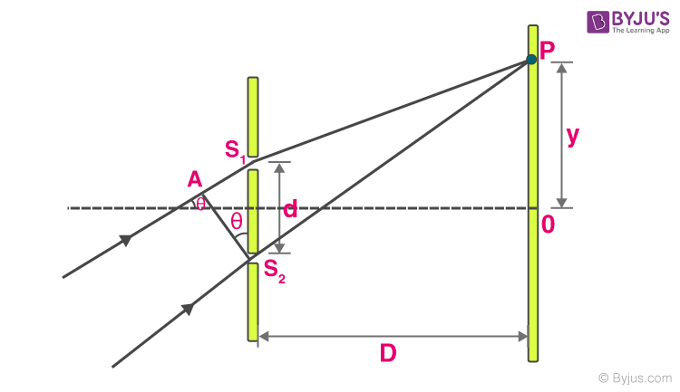
Young’s double-slit experiment uses two coherent sources of light placed at a small distance apart, usually, only a few orders of magnitude greater than the wavelength of light is used. Young’s double-slit experiment helped in understanding the wave theory of light which is explained with the help of a diagram. A screen or photodetector is placed at a large distance ’D’ away from the slits as shown.
JEE Main 2021 LIVE Physics Paper Solutions 24-Feb Shift-1 Memory-Based

The original Young’s double-slit experiment used diffracted light from a single source passed into two more slits to be used as coherent sources. Lasers are commonly used as coherent sources in the modern-day experiments.
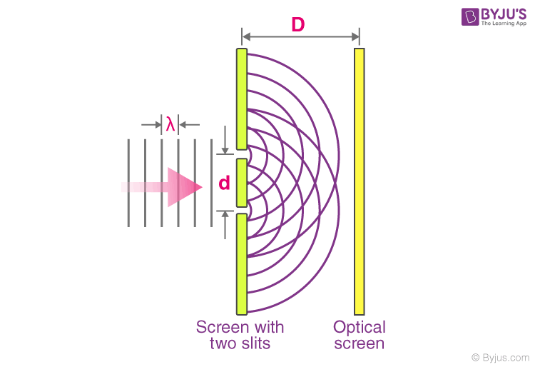
Table of Content
- Derivation
- Position of Fringes
- Shape of Fringes
- Intensity of Fringes
- Special Cases
- Displacement of Fringes
- Constructive and Destructive Interference

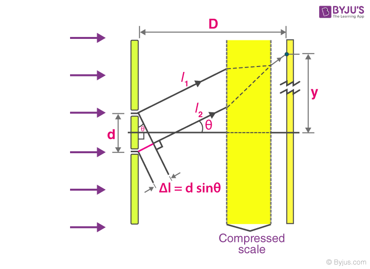
Each source can be considered as a source of coherent light waves. At any point on the screen at a distance ‘y’ from the centre, the waves travel distances l1 and l2 to create a path difference of Δl at the point. The point approximately subtends an angle of θ at the sources (since the distance D is large there is only a very small difference of the angles subtended at sources).
Derivation of Young’s Double Slit Experiment
Consider a monochromatic light source ‘S’ kept at a considerable distance from two slits s1 and s2. S is equidistant from s1 and s2. s1 and s2 behave as two coherent sources as both are derived from S.
The light passes through these slits and falls on a screen which is at a distance ‘D’ from the position of slits s1 and s2. ‘d’ is the separation between two slits.
If s1 is open and s2 is closed, the screen opposite to s1 is closed, only the screen opposite to s2 is illuminated. The interference patterns appear only when both slits s1 and s2 are open.
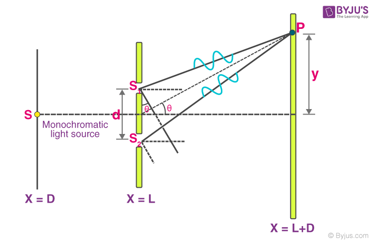
When the slit separation (d) and the screen distance (D) are kept unchanged, to reach P the light waves from s1 and s2 must travel different distances. It implies that there is a path difference in Young’s double slit experiment between the two light waves from s1 and s2.
Approximations in Young’s double slit experiment
- Approximation 1:D > > d: Since D > > d, the two light rays are assumed to be parallel.
- Approximation 2: d/λ >> 1: Often, d is a fraction of a millimetre and λ is a fraction of a micrometre for visible light.
Under these conditions θ is small, thus we can use the approximation sin θ = tan θ ≈ θ = λ/d.
∴ path difference, Δz = λ/d
This is the path difference between two waves meeting at a point on the screen. Due to this path difference in Young’s double-slit experiment, some points on the screen are bright and some points are dark.
Now, we will discuss the position of these light, dark fringes and fringe width.
Position of Fringes In Young’s Double Slit Experiment
Position of Bright Fringes
For maximum intensity or bright fringe to be formed at P
Path difference, Δz = nλ (n = 0, ±1, ±2, . . . .)
i.e., xd/D = nλ
or
x = nλD/d
The distance of the nth bright fringe from the centre is
xn = nλD/d
Similarly, the distance of the (n-1)th bright fringe from the centre is
x (n-1)= (n -1)λD/d
Fringe width, β = xn – x (n-1) = nλD/d – (n -1)λD/d = λD/d
(n = 0, ±1, ±2, . . . .)
Position of Dark Fringes
For minimum intensity or dark fringe to be formed at P,
Path difference, Δz = (2n + 1) (λ/2) (n = 0, ±1, ±2, . . . .)
i.e., x = (2n +1)λD/2d
The distance of the nth dark fringe from the centre is
xn = (2n+1)λD/2d
Similarly, the distance of the (n-1)th bright fringe from the centre is
x (n-1)= (2(n-1) +1)λD/2d
Fringe width, β = xn – x (n-1) = (2n + 1) λD/2d – (2(n -1) + 1)λD/2d = λD/d
(n = 0, ±1, ±2, . . . .)
Fringe Width
Distance between two adjacent bright (or dark) fringes is called the fringe width.
β = λD/d
If the apparatus of Young’s double slit experiment is immersed in a liquid of refractive index (μ), then the wavelength of light and fringe width decreases ‘μ’ times.
If white light is used in place of monochromatic light, then coloured fringes are obtained on the screen with red fringes larger in size than violet.
Angular Width of Fringes
Let the angular position of nth bright fringe is
⇒
Similarly, the angular position of (n+1)th bright fringe is
∴ Angular width of a fringe in Youngs double slit experiment is given by,
We know that
⇒
Angular width is independent of ‘n’ i.e angular width of all fringes are same.
Maximum Order of Interference Fringes
The position of nth order maxima on the screen is
But ‘n’ values cannot take infinitely large values as it would violate 2nd approximation.
i.e θ is small (or) y < < D
⇒
Hence, the above formula for interference maxima is applicable when
When ‘n’ value becomes comparable to
⇒
⇒
The above represents box function or greatest integer function.
Similarly, the highest order of interference minima
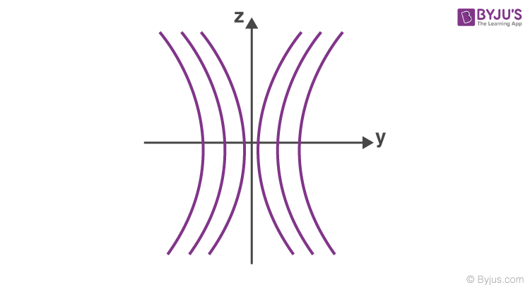
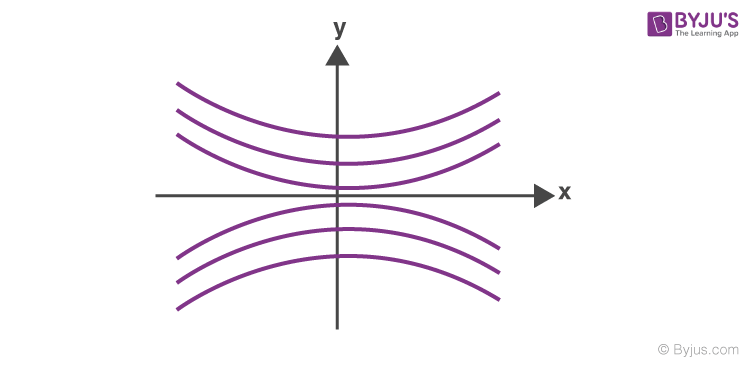
Shape of Interference Fringes in YDSE
From the given YDSE diagram, the path difference from the two slits is given by
The above equation represents a hyperbola with its two foci as s1 and s2.
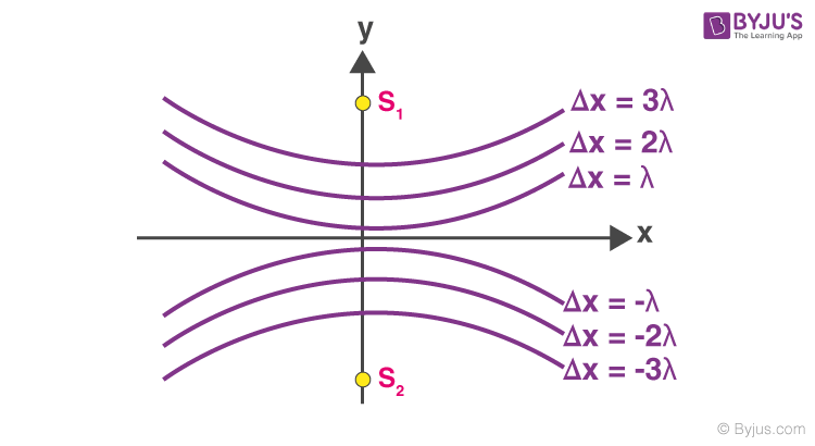
The interference pattern we get on the screen is a section of a hyperbola when we revolve hyperbola about the axis s1s2.
If the screen is yz plane, fringes are hyperbolic with a straight central section.
If the screen is xy plane, the fringes are hyperbolic with a straight central section.
Intensity of Fringes In Young’s Double Slit Experiment
For two coherent sources s1 and s2, the resultant intensity at point p is given by
I = I1 + I2 + 2 √(I1 . I2) cos φ
Putting I1 = I2 = I0 (Since, d<<<D)
I = I0 + I0 + 2 √(I0.I0) cos φ
I = 2I0 + 2 (I0) cos φ
I = 2I0 (1 + cos φ)
I =
For maximum intensity
or φ = 2nπ
phase difference φ = 2nπ
then, path difference
The intensity of bright points are maximum and given by
Imax = 4I0
For minimum Intensity
φ = (2n – 1) π
Phase difference φ = (2n – 1)π
Thus, intensity of minima is given by
Imin = 0
If
Special Cases
Rays Not Parallel to Principal Axis:
From the above diagram,
Path difference
For maxima
For minima
Using this we can calculate different positions of maxima and minima.
Source Placed Beyond the Central Line:
If the source is placed a little above or below this centre line, the wave interaction with S1 and S2 has a path difference at a point P on the screen,
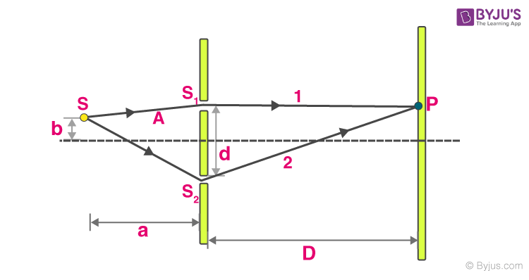
Δ x= (distance of ray 2) – (distance of ray 1)
=
=
= bd/a + yd/D → (*)
We know Δx = nλ for maximum
Δx = (2n – 1) λ/2 for minimum
By knowing the value of Δx from (*) we can calculate different positions of maxima and minima.
Displacement of Fringes in YDSE
When a thin transparent plate of thickness ‘t’ is introduced in front of one of the slits in Young’s double slit experiment, the fringe pattern shifts toward the side where the plate is present.
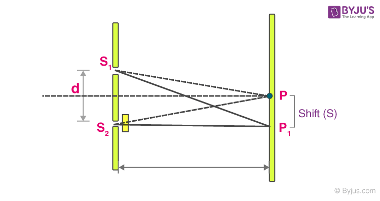
The dotted lines denote the path of the light before introducing the transparent plate. The solid lines denote the path of the light after introducing a transparent plate.
Path difference before introducing the plate
Path difference after introducing the plate
The path length
where
Then we get
Then,
Term (1) defines the position of a bright or dark fringe, the term (2) defines the shift occurred in the particular fringe due to the introduction of a transparent plate.
Constructive and Destructive Interference
For constructive interference, the path difference must be an integral multiple of the wavelength.
Thus for a bright fringe to be at ‘y’,
nλ = y d/D
Or, y = nλD/d
Where n = ±0,1,2,3…..
The 0th fringe represents the central bright fringe.
Similarly, the expression for a dark fringe in Young’s double-slit experiment can be found by setting the path difference as:
Δl = (2n+1)λ/2
This simplifies to
(2n+1)λ/2 = y d/D
y = (2n+1)λD/2d
The Young’s double-slit experiment was a watershed moment in scientific history because it firmly established that light indeed behaved as a wave.
The Double Slit Experiment was later conducted using electrons, and to everyone’s surprise, the pattern generated was similar as expected with light. This would forever change our understanding of matter and particles, forcing us to accept that matter like light also behaves like a wave.
Wave Optics
Young’s Double Slit Experiment