Circuit Diagram Explanation
A circuit diagram is a graphical representation of an electrical circuit. A circuit diagram also called an electrical diagram, elementary diagram or electronic schematic is defined as a simplified graphical representation of an electrical circuit. Circuit diagrams are used for the design, construction and maintenance of electrical and electronic equipment.
What is a Circuit Diagram?
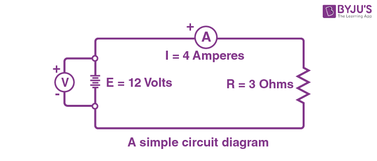
A circuit diagram is a simplified representation of the components of an electrical circuit using either the images of the distinct parts or standard symbols. It shows the relative positions of all the elements and their connections to one another. It is often used to provide a visual representation of the circuit to an electrician. The following figure shows a simple circuit diagram.

Components of Circuit Diagram
In this section, let us learn about some important circuit diagram symbols.
An electric cell: It provides the source of current. In its symbol, the larger terminal is positive, whereas the smaller one is the negative terminal.

A battery: It is a combination of cells and its utility is the same as the cell.

Switch: It is a plug key used to allow or stop the flow of current upon being pressed. It may be an open or a closed switch.

Wire joint: One device may be connected to the other using wires. This is shown by drawing ‘blobs’ at their point of connectivity.

Wires crossing without joining: The wires that do not touch each other are drawn without blobs. The following figure shows how the separated wires are represented.

Electric bulb: The electrical device which uses electricity to glow.

Resistor (R): It is used to restrict the amount of current flow in the circuit.

Variable resistance: Also known as the rheostat, it is used to regulate the amount of current flow by increasing or decreasing the resistance to the current flow.

Ammeter: It is used to measure the current passing at a particular point.

Voltmeter: It is used to measure the voltage between two points in a circuit.

Circuit Diagram Examples
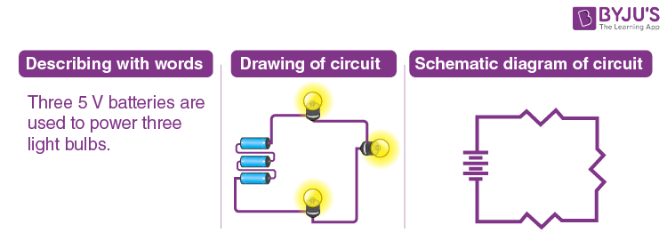
Example: Three 5 V batteries are used to power a circuit containing three light bulbs.

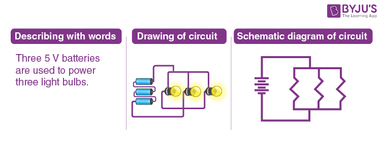
The verbal description of the circuit stated in the problem statement can be represented by drawing three lightbulbs, three cells connected by wires. The above circuit diagram presumed that the light bulbs were connected in series. But it should be noted that it doesn’t necessarily need to be connected in series. The same description of the circuit can be drawn differently as shown below:

This example illustrates the two common types of connections made in electric circuits. When two or more resistors are present in a circuit, they can be connected in series or in parallel.


Comments